Troubleshooting the
RV DSI Furnace
The following descriptions are based on the Hydro Flame 8500 series furnaces, but the operating principles are similar for other manufacturers.
Low battery voltage
The furnace is designed to operate at voltages between 10.5 to 13.5 VDC. Low voltage will not run the blower motor at the proper speed to commence the ignition sequence.
Obstructed return air intake
Return air is the air that flows in to replace the heated air that the blower pushes out through the ducting. This air is pulled in by the furnace through louvered openings in the side of the furnace cabinet, and any items stored near these openings could interfere with this air flow. More information on this here.
Obstructed exhaust
The exhaust venting must be clear of all obstructions for proper furnace operation. Inspect the vents for insect or bird nests or other debris.
Low gas pressure
Please see the manometer page for more information and a simple manometer you can build yourself!
Time delay relay

(Used on older furnaces, newer furnaces have the relay incorporated into the circuit board) This relay performs two separate jobs - one to handle the relatively high current needed to run the blower motor - and two, to allow the blower to run for 45 to 90 seconds after the thermostat is satisfied. This allows excess heat in the chamber to dissipate before the blower stops.
The relay is normally open and should always have power from the circuit breaker. Only when power from the thermostat is present does the relay close after a 20 second delay. Power then flows to the blower motor.
Blower motor
Next in the ignition sequence is the blower motor. It drives two squirrel cage fans to provide separate air flow for the combustion process and for distributing the heated air to the coach. A heat exchanger is used to separate the heat from the burning gas while preventing exhaust gases from entering the living space.
Specific motors are used in each model and BTU size of furnace and the correct replacement motor must be used.
Sail switch

The sail switch is an on/off device. (normally in the off position) It gets it's name from the "sail" or paddle that is attached to the switch mechanism. As the blower comes up to speed, it blows air onto the sail with enough force to push the switch closed, thus allowing electrical current to flow to the next component in line.
It's job is to determine if there is adequate air flow for proper combustion to take place. If the battery voltage is low or the fan does not come up to 75 per cent of it's design speed, the sail switch will not close.
Possible causes of this malfunction are: low battery, restricted return air inflow, restricted or inadequate outlet vents, restricted combustion air inlet or exhaust, faulty sail switch.
Limit switch

The limit switch is a simple temperature controlled switch. It's function is to monitor the combustion chamber heat level. If the temperature of the combustion chamber exceeds the preset limit, the switch will open and disrupt the flow of current to the circuit board, in effect, shutting down the main burner. Once the chamber temperature cools sufficiently, the limit switch resets. This initializes the ignition sequence and starts another cycle. This condition is referred to as "limiting".
Circuit board

The circuit board will not receive power until the sail switch is closed by adequate air flow from the blower. The power must also flow through the limit switch and the sail switch.
When the circuit board is triggered by this current, it delays ignition for about 15 seconds to allow the blower to purge the combustion chamber of any unburned gases.
The circuit board then sends high voltage pulses to the electrode assembly, providing a series of sparks to ignite the gas/air mixture. A rapid ticking noise can sometimes be heard as the igniter is sparking.
At the same time, the circuit board sends power to open the gas valves allowing the fuel to flow to the burner.
The circuit board monitors the burn cycle through a sensor that detects the presence of the flame. If the sensor does not detect a satisfactory flame within about 10 seconds, the board then shuts off the gas valves and discontinues the ignition spark. All electrical connections should be clean and tight. I have often solved a misfire problem by simply cleaning and inspecting every electrical connection, especially the sensor/electrode wire. The sensor sends a microamp reading to the circuit board when the flame is burning. Any impedance to this tiny amperage flow will cause the board to shut things down.
Depending on the board design, it will try for ignition up to three times. Beyond that point, it goes into lockout mode, will not retry for ignition until reset and the blower will continue to run. Newer circuit board designs will try for ignition three times and then shut everything down to prevent the battery from running down.
Burner assembly

This unit is removed as an assembly consisting of the burner head, the gas valve and the electrode
Note that different furnace models use a different burner head. The correct replacement part must be used.
Electrode assembly

The electrode is the device that allows high current from the circuit board to jump the gap between the electrode probes causing an ignition spark.
The electrode gap should be 1/8th inch as shown.
The electrode also serves as a sensing device to tell the circuit board that the flame is present.
Thermostat

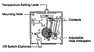
The thermostat is an on/off switch controlled by a bi-metal coil (or an electronic circuit) that senses the changes in temperature and
opens or closes an electrical contact. This signal is sent to the furnace to start or stop the heating cycle.
Digital thermostat upgrade
Gas Valve
A White Rogers dual solenoid gas valve is used on these furnaces. The solenoid coils can be replaced individually if they become defective. Each coil should measure about 30 to 50 ohms.
Diagram of the Sequence of Events for a DSI RV Furnace
Atwood Furnace Error Codes
- Fault LED Indication
- Internal Circuit Board fault - Steady on, no flashing
- Limit switch/Airflow problems - 1 flash with 3-second pause
- Flame Sense fault - 2 flashes with 3-second pause
- Ignition Lockout Fault - 3 flashes with 3-second pause
See the RV Manuals page for factory manuals.
Also see Furnace cautions page for more.